THE SPECIFIER
a hexagonal-grid based mechanical-CAD tool
Hexagonal-grid based 3D-surface design
Modern MCAD tools represent 3D surfaces as meshes of flat triangles,
or a set of NURBS control-points.
Specifying a 3D-surface by directly editing traingle-vertices or NURBS control-points is a time-consuming process, hence all MCAD tools provide parameter-driven high-level shape input mechanisms using a "geometry-modeler".
Pre-designed meshes for commonly used 3D-shapes such as cyclinders, spheres, strips, fixed cross-section extrusions etc., are provided and their generation can be controlled via input parameters.
Any shape can be transformed using a palette of provided 3D transforms and
negative space techniques enable removing a shape from another shape.
The tool maintains a history of design changes, and past designs, common designs and commercial off-the shelf designs can be re-used in a new design.
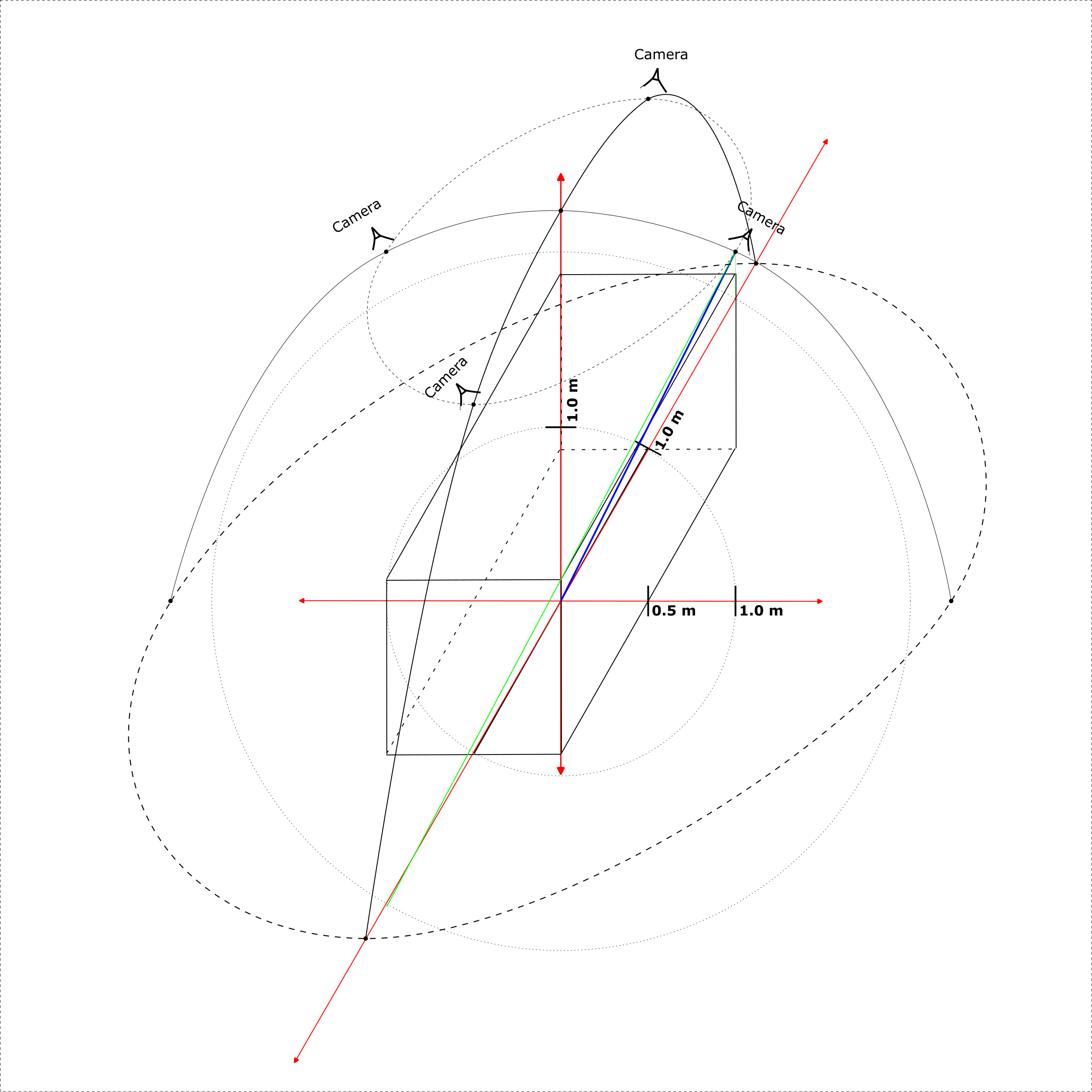
The Specifier uses a hex-grid to specify angles, and to estimate curves and 3D curved-surfaces.
Since a surface is represented as a set of (discrete) points on a hex-grid,
(instead of floating point coordinates on a cartesian plane),
it becomes much simpler to specify a 3D structure or structural-assembly.
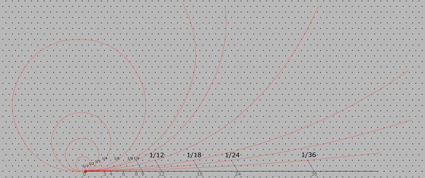
The illustration above demonstrates constant-curvature curves rendered on a hex-grid. Curvature on a hex-grid can be specified using a single integral ratio. The illustation displays piecewise-linear segments drawn using a native 2D graphics library.
Mechanical CAD domain review
The first MCAD tool was introduced in 1997 and since then 4 major tool vendors -- Dassault Systems, Autodesk, Siemens and PTC have evolved these tools and integrated them into computer-aided assembly line manufacturing processes. These production management tool integrated MCAD tools are currently used by most large manufacturers. Solidworks/CATIA by Dassualt Systems, SolidEdge/NX by Siemens, Inventor by Autodesk and CREO by PTC are well-known examples.
In addition, there are several active (non-integrated) MCAD tools for smaller scale design and manufacturing.
These tools are MCAD only, and hence simpler, easier-to-use, and include collaborative design capabilities and specialised modeling capabilities, such as NURBS.
They are also quite interoperable.
Standardisation of a structural-assembly model exchange file format by the ISO (STEP-10303), has helped with interoperability for such non-integrated tools.
The first tools -- digital exchange and pre-production visualisation
The first MCAD product, was a Windows app designed to run on an advanced PC-workstation,
with specialised 3D graphics and large high-resolution screens.
It used keyboard and mouse input to enable a user to input the 3D specifications of objects.
These inputs could be visualised through a camera-view on a 2D screen.
The purpose was to enable digital exchange, between designer, prototyper and production-unit.
A digital specification could be used directly to control computer aided manufacturing tools.
A design could also be visualised before production.
Even today, MCAD tools are primarily used for digital exchange and pre-production visualisation.
Digital-first design
Over time, libraries of specified objects developed
and major advancements were made in geometric modelling. The specification tool could now also be used as a design tool and digital-first design started, to an extent.
Digital-first design introduces a gap between design and produceability,
that has to be bridged.
A digital-domain design has to be verified for its physical performance parameters,
and each production iteration is usually expensive.
A traditional physical-prototype-update based design-process is lot cheaper and more efficient.
3D printing is a new technology that is directly connected to digital-first design.
Tool specialisation -- physics-based simulation, domain specialisation, NURBS
Some virtual physics-based simulation capabilities,
such as finite-element-analysis, and motion and kinematic analysis were introduced.
This improved the predictability of a design's real-world performance.
Another direction of MCAD tool specialisation was production-technique specific modeling,
such as weldments and sheet-metal production guidelines.
This improved production efficiency.
To model mathematically smooth curved surfaces, NURBS-based modelling also started being used.
Small-scale MCAD tools
From a designer's standpoint, MCAD tools are characterised by their geometry kernel.
Examples of geometry kernels, currently in use, are Parasolid (Siemens), 3D ACIS Modeller (Spatial), ShapeManager (Autodesk), Granite (PTC), Convergence Geometric Modeller (Dassault) and openNURBS (Rhino3D).
For new product designs associated with prototyping or small-scale production processes, the following MCAD tools are commonly used.
The most commonly used tool
Solidworks
![]()
Platform: Windows or Cloud
Geometry Kernel: Parasolid
Launch date: 1995
Annual revenues (estimated): $1.5B
Location: MA, USA
Cloud-based collaboration enabled tools for smaller scale industrial-design
PTC OnShape
![]()
Platform: Saas on Cloud
Geometry Kernel: Parasolid
Launch date: 2012
Annual revenues (estimated): $245M
Location: MA, USA
Autodesk Fusion360
![]()
Platform: Windows, MacOS, Cloud
Geometry Kernel: ShapeManager
Launch date: 2013
Annual revenues (estimated): $20M
Location: CA, USA
Established MCAD tools for very small-scale industrial-design
Alibre
![]()
Platform: Windows only
Geometry Kernel: Parasolid
Launch date: 1997
Annual revenues (estimated): $12.6M
Location: TX, USA
IronCAD
![]()
Platform: Windows only
Geometry Kernel: Parasolid or ACIS
Launch date: 2001
Annual revenues (estimated): $5M
Location: GA, USA
Niche MCAD tools (ease-of-use and NURBS based modeling)
Shapr3D
![]()
(ease of use)
Platform: iPadOS + Pen, AppleVision Pro, Windows, MacOS
Geometry Kernel: Parasolid
Launch date: 2013
Annual revenues (estimated): $14.6M
Location: Hungary
Rhino3D
![]()
(NURBS modeling)
Platform: Windows, MacOS
Geometry Kernel: openNURBS
Launch date: 1998
Annual revenues (estimated): $13.1M
Location: WA, USA
Specifier 1.0: differentiating features
Specifier 1.0 targets new design and prototyping,
and fits more efficiently into a design-prototyping process than any existing tool.
Use-centric design.
The Specifier is being designed in sync with the design of a bicycle-trailer prototype.
Hence it's design is use-centric and domain specialised, which makes it an efficient addition to a specific design-prototyping process.
Simplicity.
The Specifier uses InterUnit-UI  , instead of WIMP, which makes it far simpler to use.
InterUnit-UI is a new design paradigm that has far better ergonomics than WIMP.
Most existing tools are not that simple to use (they all use WIMP).
, instead of WIMP, which makes it far simpler to use.
InterUnit-UI is a new design paradigm that has far better ergonomics than WIMP.
Most existing tools are not that simple to use (they all use WIMP).
Shapr3D is a recent tool that has been specially designed for ease of use.
Some ergonomic modelling.
Includes some ergonomic modeling of the user of the design.
Hardware friendly.
The Specifier uses a hexagonal grid as an underlying graphic design basis, and implements a specially designed hex-grid graphics library.
This library implementation does not rely on 3D hardware acceleration,
and uses a platform's native 2D drawing library instead.
It is also designed with a minimal feature-set and resource usage approach.
These implemntation choices make The Specifier's computational complexity a lot lower
and it will be very responsive on average PC hardware as a native app.
(Most existing tools are either native, requiring workstation class processors,
or cloud-based, implying browser and internet-bandwidth constraints).
The Specifier does not have any server side execution components (like cloud based tools).
Licensing
Khitchdee Design ( ) plans to license the Specifier to industrial-designers and prototype developers.
3D object-visualisation on a PC display (technology review)
Mechanical CAD tools require a mechanism for visualing 3D objects on a 2D display.
We present a brief review of the technology involved and the major products offered
Design and Design-specification
We focus on structural design and the design of metal-based structures.
Below is a description of the design specification process for a structural-assembly.
The Hexagonal-grid as a CAD tool development aid
A Hexagonal grid is like an extended virtual protractor
(the instrument used to measure angles).
It can be used to choose or specify angles and curves in a mechanical CAD process.
What is design-specification?
There are 2 aspects to the specification of a land-vehicle design.
- A structural specification.
A static description of the built up structure of a design.
It includes a specification of each part in a design,
how the parts connect with each other,
and a structural model of the user (if applicable).
- A construction-process specification.
Specifies the construction-process of a design.
How each component in the design is contructed
and how the components are put together to produce the design.
This is useful for an assembler or a fabricator.
What is specification visualisation?
A (design-specification) Visualiser implements perspective-correct display-screen mapping of modelled 3D objects.
Our visualiser models a camera with a location and orientation,
and a single light source, at the same orientation and location as the camera.
We represent a 3D object as its outer surface,
a lattice of 3D planar segments.
We map these 3D planar segments onto a 2D screen using 4-point plane-mapping.
A curved plane (in 3D) is modelled as a lattice of flat planes.
Our visualiser uses only the device's (2D) drawing engine,
and targets a visualisation time of 100ms/frame
for a bicycle-model at 4K resolution on an Snapdragon 8 Gen 5 SOC class device.
Construction-process specification in the Specifier (planned)
We plan to produce a construction-processes specification component
after the structural specification component.
The designer will identify several construction states in the construction process.
Each construction state will be a physical model of the relative placement of the components and tools in the process.
The designer will indicate transitions between construction states.
The construction-process specifier will use these construction states and transitions between them
to create an interpolated sequence of models to be visualised.
This sequence will be visualised using the Visualiser with some animation controls.
Photograph assisted specification in the Specifier (planned)
After the mouse and keyboard specification interface,
we plan to produce an additional interface to improve structural specification input efficiency.
This interface will work as follows:
- A designer loads photographs of a real object into the app
(with a description of the approximate camera parameters used in taking those photographs). - Identifies (in terms of 2D point descriptions) the components in the structure of the object in the photograph.
- For each component, they describe its 3D orientation and size, based on physical measurements.
Structural overview of a bicycle
A bicycle is specified as a primary frame and components,
attachment mechanisms between them,
and additional braking and gear-ratio control systems.
A. The primary frame and components.
- A frame consisting of:
A head-tube, top-tube, down-tube and seat-tube.
A seat-stay and a chain-stay at the back.
A bottom bracket at the base of the frame.
Connectors that connect the parts in the frame. - The front fork and handle-bar
- The chain-drive consisting of:
a chain crank and pedals
a freewheel
a chain - The front-wheel, front-wheel spindle and tire
- The rear-wheel, rear-wheel spindle and freewheel attachment, and tire.
B. Attachment specifications between the primary frame and components.
C. The braking system and optional gear-ratio control systems.
- A braking system and its attachment mechanism
- A gear-ratio control system and its attachment machanism